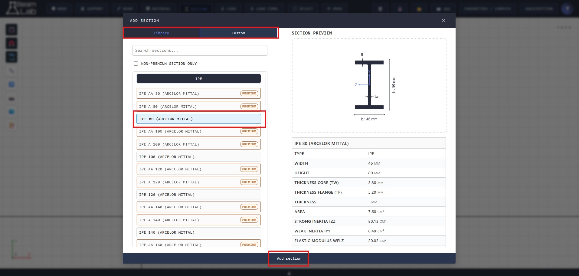
Modeling Elements
This section covers the core structural components you need to build your FEM model. Start with nodes, add supports, define beams or arcs, and assign materials and sections.
Add a Node
Nodes are the base entities of every BeamLab model. Supports, beams, arcs, and nodal loads all reference node IDs.
Creation Modes
BeamLab supports two practical node entry workflows:
- Canvas Click Mode: click directly in the workspace while Node mode is active to create nodes interactively.
- Command Prompt Mode: type coordinates as X,Y, for example 1000,500, then press Enter.
- Arc-Assisted Node Creation: during arc workflows, BeamLab can request missing nodes from geometric picks and may reuse an existing nearby node when one is detected.
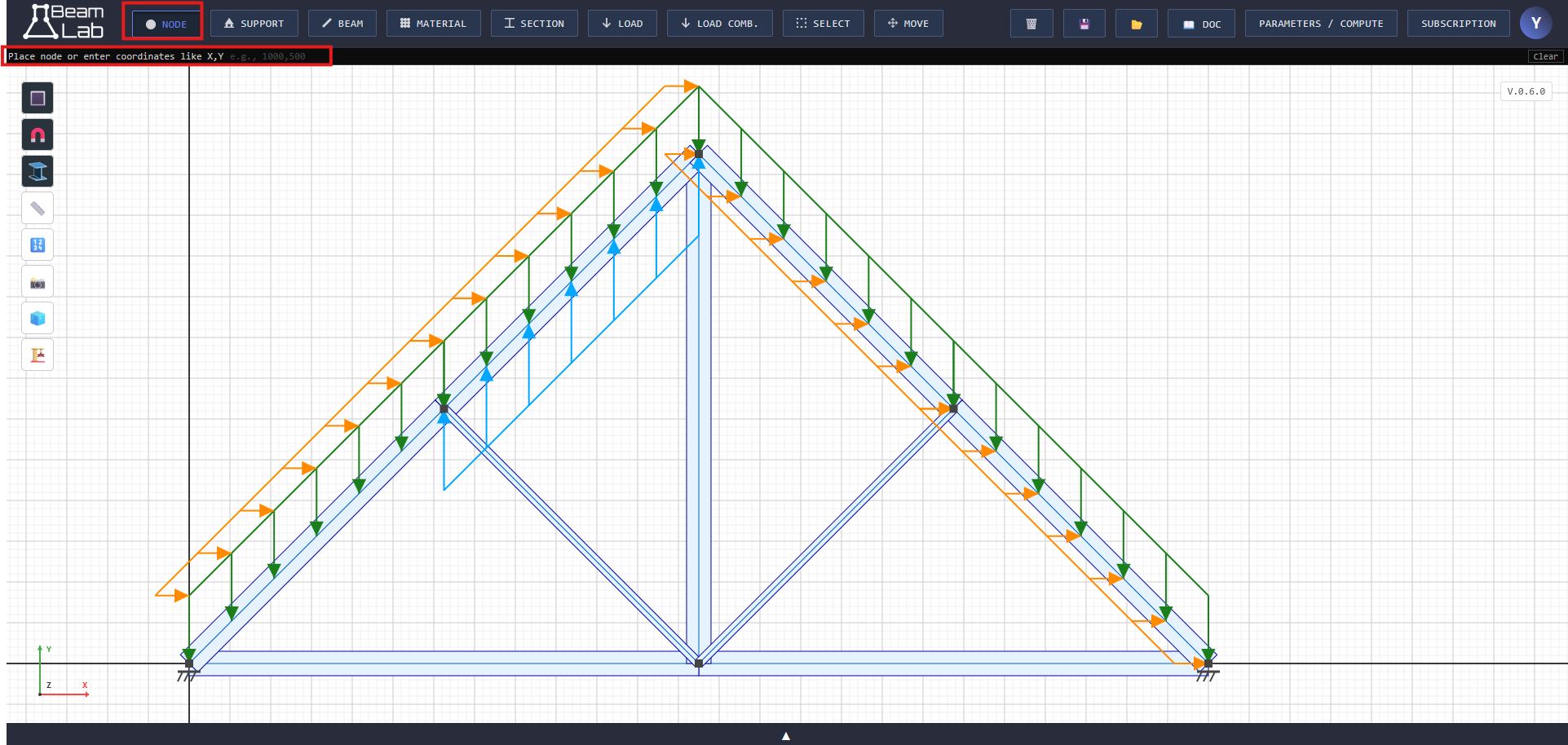
Grid Snap
When grid magnetism is active, node coordinates are snapped to the model grid. In the current implementation, snap rounding uses a 20-unit step for X and Y. Activate or desactivate the grid snip using the tool on the left side. By default, grid snap is on.
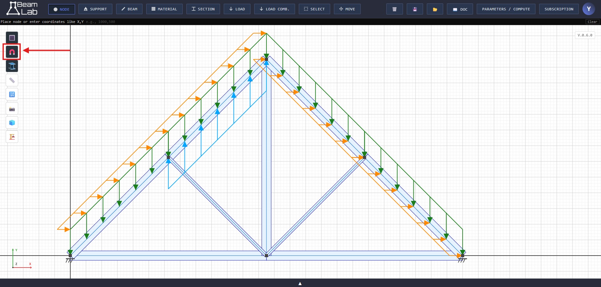
Free Plan Limit
BeamLab checks account and subscription access before creating nodes. Free usage is limited to 10 active nodes. If the limit is reached, the app displays a message inviting the user to sign in and subscribe for larger models.
Node Data-table
The Node table is designed for fast numeric editing:
- Editing X/Y cells updates the canvas immediately.
- Pasting from spreadsheet tools is supported, but this feature is still under development.
- Comma decimals are accepted and normalized.
- Press Enter to validate a cell, Escape to cancel current cell input.
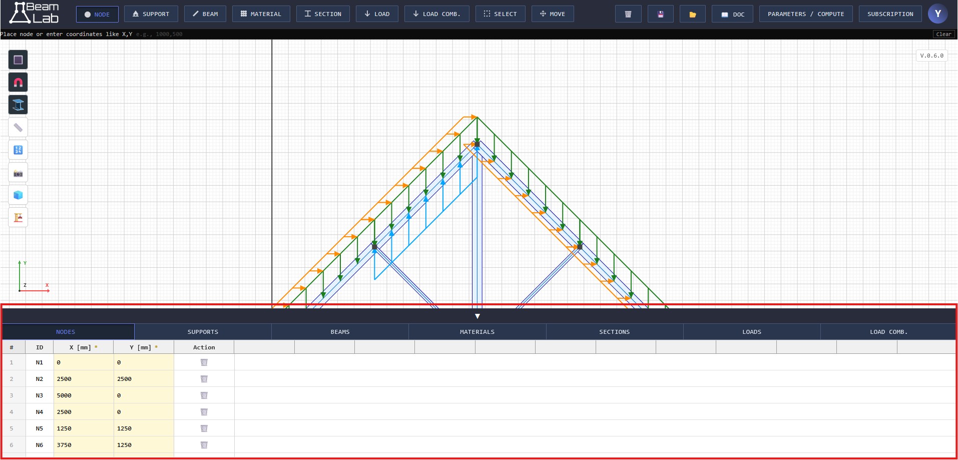
Delete a Node
You can delete a node using the data-table. BeamLab asks for confirmation if the node is connected to a beam or a load and then removes associated entities to keep the model consistent. You can also use the select tool and delete the node.

Add a Support
Supports are attached to existing nodes and define displacement and rotation constraints for the solver. BeamLab stores each support with its type, node ID, DDL state (Ux, Uy, Teta_Z), optional angle, and optional stiffness values for spring behavior.
Creation Modes
BeamLab supports two equivalent ways to create supports:
- Canvas Mode: select a support type in the sub-header, then click a node in the model.
- Command Prompt Mode: enter a node ID such as N1 or 1, then validate from the command prompt.
If no support type is selected, support creation is blocked until a type button is chosen.

Replace Existing Support
Only one active support is allowed per node. If a support already exists on the target node, BeamLab asks for confirmation before replacing it with the new type.
Support Details
The main support families are:
| Icon | Support type | Ux | Uy | Teta_Z | Description |
|---|---|---|---|---|---|
 |
Roller | Free | Blocked | Free | Restrains one translation direction while allowing movement in the orthogonal direction and free rotation. |
 |
Pin | Blocked | Blocked | Free | Restrains translations and allows rotation. |
 |
Fixed | Blocked | Blocked | Blocked | Restrains translations and rotation. |
 |
Spring | Free | Free | Free | Adds translational or rotational stiffness for semi-rigid behavior or soil interaction. |
 |
Slider | Blocked | Free | Blocked | Allows guided displacement along a defined direction while restraining other components. |
Support Data-table
The Support table rows and allows full support editing directly in place:
- Type selection via dropdown: Roller, Pin, Fixed, Slider, Spring.
- Node ID editing with validation against existing nodes.
- DDL editing with immediate redraw.
- Creation from empty rows when row data is entered.
- Persistent storage in local project data.

Angle and Spring Stiffness
Supports can be rotated using the Angle [°] field.
For spring supports, enter stiffness values in the kx, ky, and km fields. These values define the translational and rotational stiffness of the spring support. If no stiffness values are provided, the support will behave as a free support in all directions.
You can also simulate a fixed support by assigning very high stiffness values, or combine a standard support type with spring stiffness to model semi-rigid behavior.
Delete a Support
Supports can be removed with the delete action in the support table. The canvas and stored model data are updated immediately after deletion.
Add a Beam
Beam creation is available in the Beam tools. Use it after creating nodes and assigning suitable supports.
Linear Beam
Use Add beam to connect two nodes with a straight element. Straight beams form the primary structural skeleton of your model and transmit forces along the element centerline.

Subdivide Beam
Use Subdivide beam when you need additional internal nodes for local loading or response precision. This splits an existing element into smaller sub-elements while maintaining connectivity. Subdividing improves accuracy for distributed loads and refines the internal force resolution. In the free plan, you cannot subdivide a beam to create more than 10 nodes.
Arc Beam
Arc tools allow curved members with several definition methods:
- Center-Start-Angle: define the arc by its center, start point, and rotation angle.
- Three-Point Arc: click three points to define an arc geometry.
- Start-End-Radius: specify start point, end point, and radius of curvature.
This is useful for curved frames, arched members, and non-linear geometry layouts. BeamLab may automatically create intermediate nodes during arc definition if needed for discretization.

Add a Material
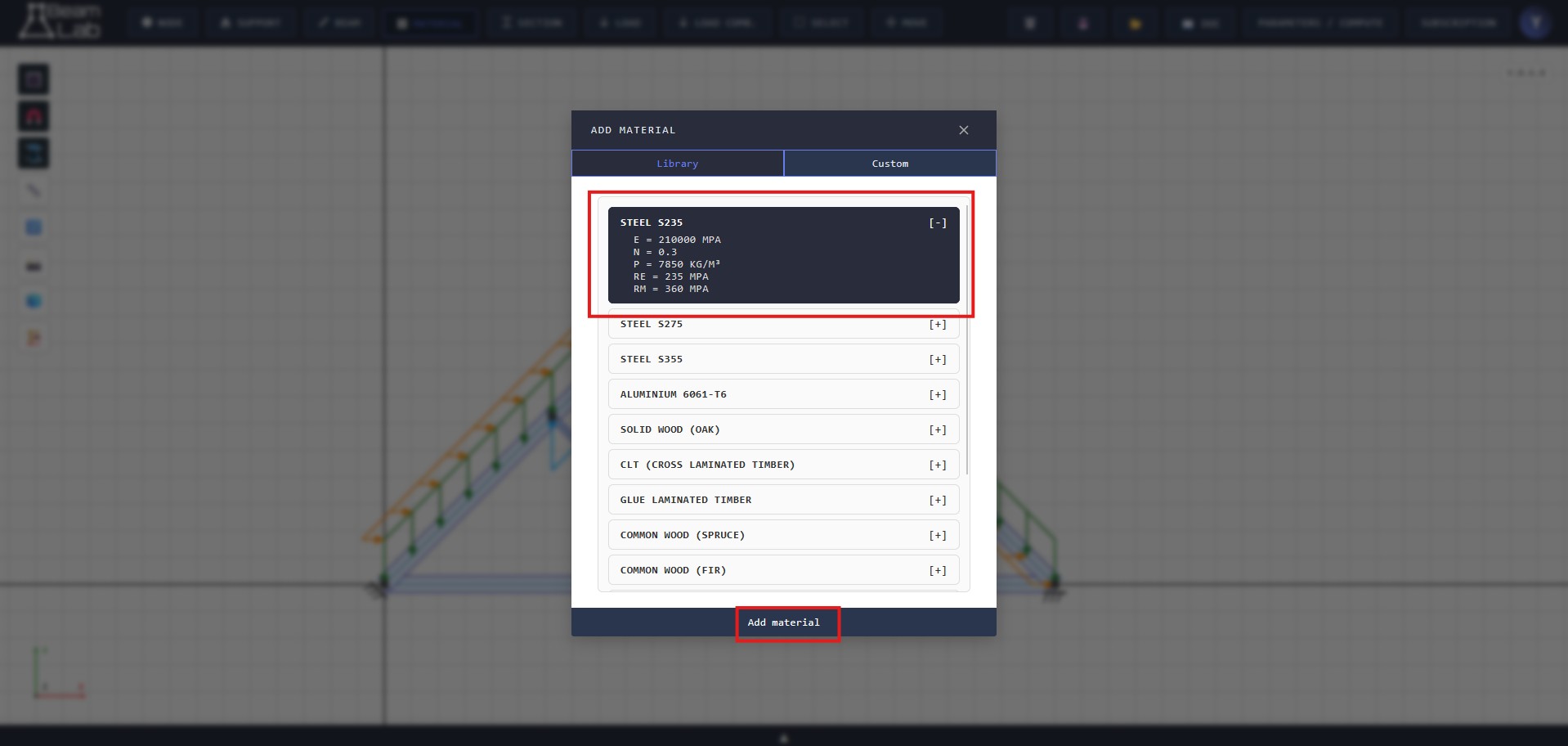
Define or select material properties such as Young's modulus (E), density, and Poisson's ratio. Material assignment controls element stiffness and, when relevant, load effects related to mass. BeamLab maintains a library of common materials for quick access and allows custom material definitions.
Some properties are mandatory for analysis, such as E, while others are optional, such as density and Poisson's ratio.

Add a Section
Choose from BeamLab predefined sections and assign them to elements. Section properties such as area A, second moment of inertia I, and dimensions directly influence deformation and internal force distribution. You can also define custom sections with custom geometric properties.
For custom sections, ensure that the area and moment of inertia are correct. The fiber coordinates are not used in the solver, but they are used for the visualization of the stress distribution in the cross-section.