
Visualization and Results
Once the analysis has run, BeamLab lets you inspect internal forces, displacements and rotations, either in the 2D or in the 3D view. This page explains how to read them, which axes they refer to, and which sign convention is used.
Global axes and local axes
Global axes
- Y is the vertical axis of the project (positive upwards). Gravity acts along -Y.
- In a 2D project, the structure is drawn in the XY plane.
- In a 3D project, X and Z are the two horizontal axes.
Local axes of a beam
Each beam has its own local axes (x, y, z), built automatically from its two nodes:
| Local axis | Definition |
|---|---|
| x | Along the beam, from its first node to its second node. |
| y | Horizontal, perpendicular to the beam: y = Y × x (Y being the vertical global axis). |
| z | z = x × y. For any non-vertical beam, z lies in the vertical plane containing the beam and points towards +Y ("up"). |
The axes always form a right-handed system (x × y = z).
The local axes depend only on the position of the nodes, not on the direction in which the beam was drawn: a horizontal beam drawn from right to left has the same z axis (pointing up) as the same beam drawn from left to right. Only its x axis, and therefore the position of its first and second ends, are reversed.
| Beam | x | y | z |
|---|---|---|---|
| Horizontal, along +X | +X | -Z | +Y |
| Horizontal, along -X | -X | +Z | +Y |
| Horizontal, along +Z | +Z | +X | +Y |
| Inclined | along the beam | horizontal | in the vertical plane of the beam, towards +Y |
| Vertical (along Y) | ±Y | -X (beam going up) or +X (beam going down) | +Z |

Vertical beams (columns)
A vertical beam is parallel to the global vertical axis, so gravity cannot define its orientation. By convention, its local z axis is the global Z axis. In a 3D project, the strong axis of a column therefore bends in the Y-Z plane unless its orientation is changed.
Strong axis and weak axis
The orientation of a section is set with the beam property orientation:
- Strong axis (default): the section is placed so that its strong axis is y. The height of the section is along z, so bending in the vertical plane (rotation about y) uses the strong-axis inertia Iyy. The weak axis is z.
- Weak axis: the section is turned by 90° about the beam axis. Bending in the vertical plane then uses the weak-axis inertia Izz.
In a 2D project, there is a single bending plane (the plane of the structure). It uses Iyy with a strong-axis orientation and Izz with a weak-axis orientation.
Rotating a structure
Results are invariant when the structure is rotated about the vertical axis Y (loads rotated with it). For a rotation about any other axis (for example about Z in a 2D project), the structure is no longer in the same position with respect to the vertical: the axial force N, the torsion T, the reactions and the displacements are unchanged, but the sign of the shear forces and bending moments of a member can change, because its "top" fibre is not the same any more.
Sign convention
All results follow one consistent convention, summarized in the figure below.
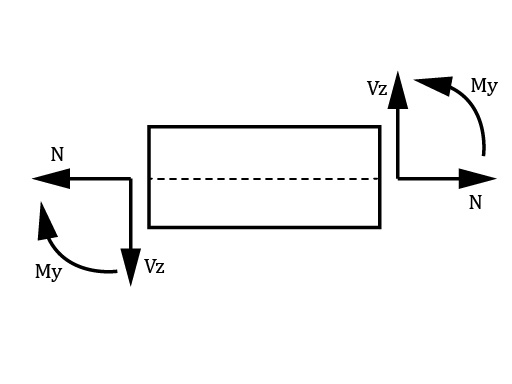
| Result | Positive when… |
|---|---|
| Normal force N | Negative values correspond to compression, positive values to tension. |
| Bending moment M (My) | A positive moment compresses the top fibre of the beam, i.e. the fibre on the +z side of the local axes (towards +Y for a non-vertical beam). |
| Shear force V (Vz) | V derives directly from the bending moment (V = dM/dx), so it has the same sign as the bending moment. |
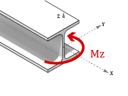
| Out-of-plane bending moment (Mz, 3D) | Same rule, in the horizontal plane: a positive moment compresses the fibre on the +y side. |
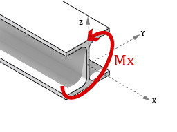
| Torsion moment T (Mx, 3D) | Right-hand rule about the local x axis. |
Warning
"Top fibre" is defined with respect to the local axes of the beam, not with respect to the screen. For a horizontal or inclined beam it is the +Y side. For a vertical beam, there is no "up" side, and the sign depends on the convention above (local z = global Z). Always check the local axes of the member (and the orientation of its section) before interpreting the sign of a result. The local axes can be displayed in the 2D and 3D views.
Curved beams (arcs)
An arc is split into straight segments, and each segment has its own local axes. Where the tangent of the arc becomes vertical, the sign of the shear force and of the bending moment can change from one segment to the next, because the z axis switches to the other side of the arc. The internal forces themselves are continuous, only their sign convention changes.
Internal forces in beams
General principles
Internal forces are expressed in the local coordinate system of each beam (see above):
- x runs along the beam, from its first node to its second node;
- y and z are the transverse axes of the cross-section.
The diagrams are plotted along each member, and the values at both ends of a member are the forces that the rest of the structure transmits to it.

Forces and moments are related to each other:
- the shear force is the derivative of the bending moment along the beam;
- a distributed load makes the shear force vary linearly (for a uniform load), and the bending moment vary parabolically.
Forces available in 2D
In a 2D project, three internal forces are available. They are the forces of the bending plane, which is the plane of the structure (XY): the shear force is named Vz and the moment My, as for the vertical plane of a 3D beam.
| Force | Symbol | Description |
|---|---|---|
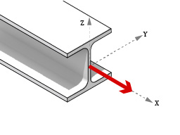
| Normal force | N | Axial force along the beam. Negative in compression. |
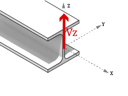
| Shear force | Vz | Transverse force in the plane of the structure. Same sign as the bending moment. |
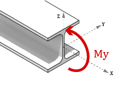
| Bending moment | My | Bending in the plane of the structure. Positive when the top fibre (+Y side) is compressed. |
Normal force (N)
Shear force (Vz)
Bending moment (My)
Additional forces in 3D
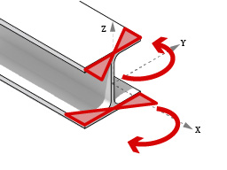
A 3D project adds the out-of-plane forces (the bending in the horizontal plane) and the torsion. Warping models also provide the bimoment.
| Force | Symbol | Description |
|---|---|---|
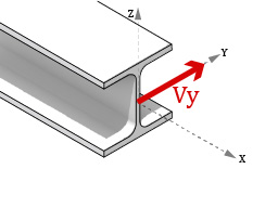
| Shear force (out of plane) | Vy | Transverse force along the local y axis (horizontal plane). |
| Bending moment (out of plane) | Mz | Bending about the local z axis. |
| Torsion moment | T (Mx) | Twisting moment about the beam axis. |
| Bimoment | B | Warping effect. Available only with warping beam models (7 DOF per node). |
In 3D, Vz and My are the forces of the vertical plane (for a non-vertical beam), and Vy and Mz those of the horizontal plane.
Shear force (Vy)
Bending moment (Mz)
Torsion moment (Mx)
Bimoment (B)
Displacements and rotations
General principles
Displacements are expressed in the global coordinate system of the project (X, Y, Z), not in the local axes of the beams. This guarantees that two beams sharing a node always show the same displacement at that node.
- Displacements are shown in mm.
- Rotations are shown in mrad.
- Diagrams are drawn with a color scale (from green to red) that goes from the smallest to the largest displayed value.

Available components
| Project type | Displacements | Rotations |
|---|---|---|
| 2D | Ux, Uy, and U (total displacement) | One rotation: θz |
| 3D | Ux, Uy, Uz, and U (total displacement) | Three rotations: θx, θy, θz |
Note
In the presence of a hinge or a semi-rigid connection, the rotation of the node and the rotation of the beam end are different. The rotations displayed are those of the beam ends.
Wireframe or full view
The deformed shape can be displayed either:
- as a wireframe (the beams are drawn as lines), or
- as a full view (the beams are drawn with their actual cross-section).
The wireframe view is available only when the material is custom.
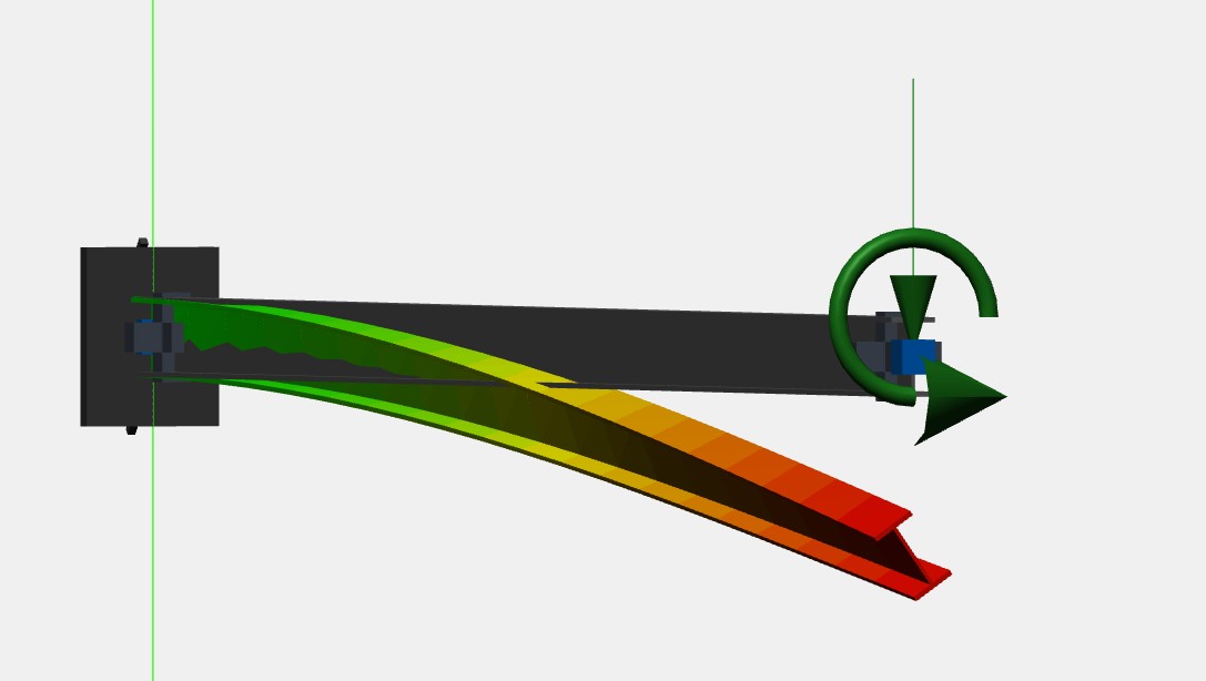
Twist of the beams
In 3D projects, when a beam undergoes a torsional rotation, its twist can be visualized in the 3D view: the cross-section rotates progressively about the beam axis along its length. Twist visualization can be disabled in the legend.
Warning
The deformation display is amplified by the same factor as shown in the legend. If the rotation is significantly greater than the beam's displacement, visual artifacts may appear. If this is the case, it is best to disable the rotation display and check the model.
Export to Excel
Info
Exporting to Excel is available to premium users only.
The exported workbook contains the full description of the project and its results, organized in several sheets:
| Sheet | Content |
|---|---|
| Model Summary | Project name, units, analysis type. |
| Nodes & Supports | Node coordinates, support types, reactions. |
| Elements & Properties | Beam definitions, materials, sections. |
| Load Cases | Load definitions and combinations. |
| Results | Displacements, internal forces and stresses for all combinations. |